Example 1:Before setting up the equilibrium equations to solve for the support reactions, an appropriate free-body diagram of the structure must be drawn to identify all the known and unknown forces acting on the structure. We should keep in mind that if a structure is in the state of equilibrium, then every part of that structure has to be in equilibrium as well. Therefore, if the free-body diagram of the whole or part of the structure is drawn correctly, then it should demonstrate the condition of equilibrium.
For a truss structure, we are normally interested in two separate free-body diagrams. The free-body diagram of the truss as a whole is used for the calculation of reactions, and another set of free-body diagrams is used for the calculation of member forces. We will discuss the latter case in a later section. Let us now develop the free body diagram of a truss for the calculation of its support reactions.
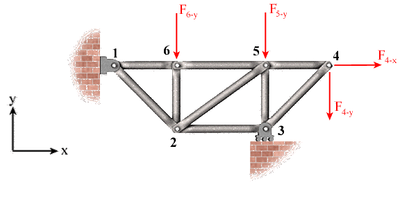
The nine-bar truss shown below is supported at joints 1 and 3 and is loaded at joints 4, 5, and 6.

Move the mouse over the figure to see the
free-body diagram
Solution:Since we are interested in calculating the support reactions, it is not necessary to show all the internal details of the truss in the free-body diagram. To demonstrate this fact, the internal members are shown in light gray color in the free-body diagram.
Joint 1 is pinned. Thus, its movements in x and y directions are restrained. Joint 3 is supported by a roller in the horizontal plane, which restrains its movement only in the
y direction. Consistent with this fact, the free-body diagram of the truss shows two reactions at joint 1 and one reaction at joint 3.
It is a good practice to show the reactions in the positive x and y directions. With the help of the equilibrium equations, we solve for the unknown reactions. If a reaction force is found to be a negative number, then its true direction is opposite to that shown in the diagram.
The equilibrium of forces in the x direction is expressed as
| S Fx = 0 |
=> |
R1-x + F4-x = 0 |
=> |
R1-x = - F4-x |
Thus R1-x is in the negative x direction because of the negative sign in front of its magnitude.
Using the counter-clockwise rotation as positive, the equilibrium of moments about joint 1 is expressed as
| S M1 = 0 |
=> |
R3-y (x3 - x1) - F4-y(x4 - x1) - F5-y(x5 - x1) - F6-y(x
6 - x1) = 0 |
| |
=> |
R3-y = [F4-y(x4 - x1) + F5-y(x5 - x1) + F6-y(x6 - x1)] / (x3 ñ x1) |
The positive value of R3-y indicates the assumed direction is correct. The equilibrium of forces in the y direction is written as
| S F = 0 |
=> |
R1- + R3-y - F4-y - F5-y - F6-y = 0 |
| |
=> |
R1-y = - R3-y + F4-y + F5-y + F6-y |
Once again, the positive value of R1-y indicates the assumed direction is correct.
