


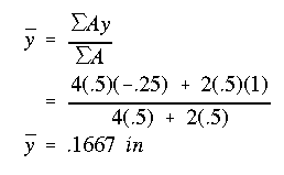
Using line b-b as reference, with positive direction downward, the y centroidal coordinate is determined as
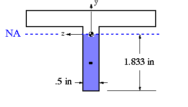
Since the beam is elastic, the netrual axis will pass through its cross-sectional centroid. The moment that force P produces is about the horizontal axis, therefore, neutral axis coincides with the horizontal centroidal axis in this problem as shown in the figure below.
The applied load puts the portion above the NA in tension and the one below in compression.
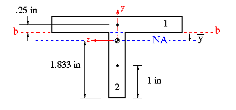
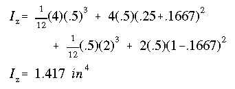
The moment of inertia about the horizontal centroidal axis is the only one that is needed to be calculated here, and is determined as
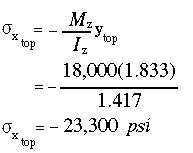
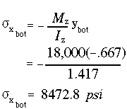
(a) The maximum compressive stress will occur at the farthest point from the NA, on the compression side. At section n-n the bending moment is

The corresponding compressive stress will be
(b) The maximum tensile stress will occur at the farthest point from the NA on the tension side.
(c) As was explained earlier, the shear stress should be viewed as the ratio (V/I) times the ratio (Q/t). At a given section along the length of the beam (V/I) is constant. This means that the maximum shear stress will occur at the point on the cross section which results in the largest (Q/t) value.
Without any exception, the first moment of area, Q is always maximum at the NA. Since in this cross section the width t is also minimum at the NA, we can conclude that the maximum shear stress will occur there.
Side Note:
Based on the above discussion, it is quite possible for the maximum shear stress to occur at a point other than the NA. You must always be aware of this fact when analyzing a beam under transverse shear loads.
To determine Q, cut the cross section horizontally at the NA and choose either the top or the bottom portion, it doesn't matter which because the same answer will result using either portion. Therefore, it makes sense to pick the portion with the simplest shape to calculate Q, in this case the bottom portion.
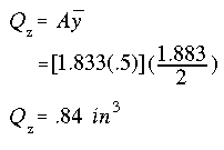
The maximum shear stress on the transverse plane n-n is found to be
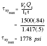
The shear stress distribution over the entire cross section was not asked for in the problem statement, but it is shown below for completeness.
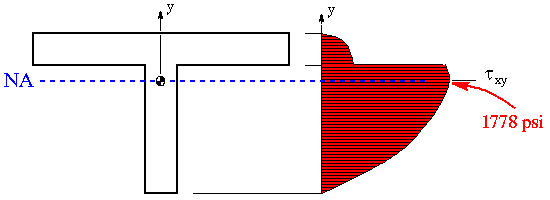
Notice that the shear stress distribution shows only one component of shear stress (i.e., the vertical component). While this component is the dominant one along the vertical flange, it is the smallest one along the horizontal flanges. To determine the dominant component of shear stress along the top flanges (i.e., horizontal component), we must make a vertical cut along either the left or the right flange (due to symmetry) and calculate Q/t along the flange. The variation of shear stress will be linear with the largest flange shear stress occuring near the junction of the three flanges. We will see this difference in later example problems. However, in this problem the overall maximum shear stress at section n-n is the one found earlier.
It is also important to point out a couple of things about the shear stress distribution shown. First, notice that the variation of shear stress is quadratic. This is governed solely by the equation for Q. Second, notice the discontinuity at the junction. This is because as we go from top to bottom surface, the thickness suddenly changes at the junction. The sharp reduction in thickness is responsible for the sharp increase in the shear stress.
 To Section
III.3
 To Index Page of
Transverse Shear Loading of Open Sections