
Two types of closed-section shear flow problems are discussed here.
In case 1, the resultant shear force passes through the shear center of the closed section. Therefore, we know that in such a loading, the beam will bend without twisting. This is referred to here as the bending problem.
In case 2, the resultant shear force does not pass through the shear center. As a result, the beam will twist as it bends. This is referred to here as the bend-twist problem.
There are two different methods to solve these types of problems. Method 1 is known as the direct method, and method 2 is known as the indirect or shear center method. These two methods of analysis are explained below.
In these problems we know that the transverse shear force passes through the shear center of the section. How do we know that? There are two possibilities. This fact may be explicitly stated in the problem statement. Else, it may be realized by examining the geometric shape of the beam cross section and where the applied load is shown to be acting. Therefore, it is obvious that beam should bend without twisting.
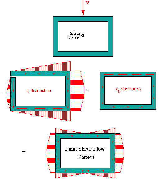
To start the analysis, assume the shear flow is zero at an arbitrary point. This implies that the section has been "cut" longitudinally at that point, thus creating a free edge. Then, we use the general shear flow equation to find the "preliminary" shear flow distribution along each wall. We designate this shear flow by q'. The reason we call this the preliminary shear flow is that it is based on the assumption that shear flow is zero at the selected point. Also, with this being a bending problem, the shear flow should result in the angle of twist of zero. If we were to use q' to solve for the twist angle, it would not result in zero twist. This tells us that the shear flow q' is not the true shear flow distribution.
To satisfy the zero-twist requirement, a constant shear flow of unknown magnitude q0 is added to the shear flow distribution q' found previously. Recall the angle of twist equation for closed sections discussed in Chapter I. We use that equation with q along each side being q' of that side + or - q0 depending on whether they are both in the same or opposite direction. By setting the angle of twist to zero we find the constant shear flow q0. This value is then added to q' values found previously to determine the final shear flow distribution, q.
These steps are graphically shown in the figure below for a doubly symmetric cross section under a vertical transverse shear force through the shear center (which in this case coincides with the cross-sectional centroid). Note the symmetry in the shear flow pattern. This is the consequence of force acting along an axis of symmetry.

If we are just interested in determining the shear flow distribution due to the resultant shear force with no interest in the location of shear center, then this is the easiest method to use. In using this method, it does not matter whether or not the transverse shear force is acting through the shear center.
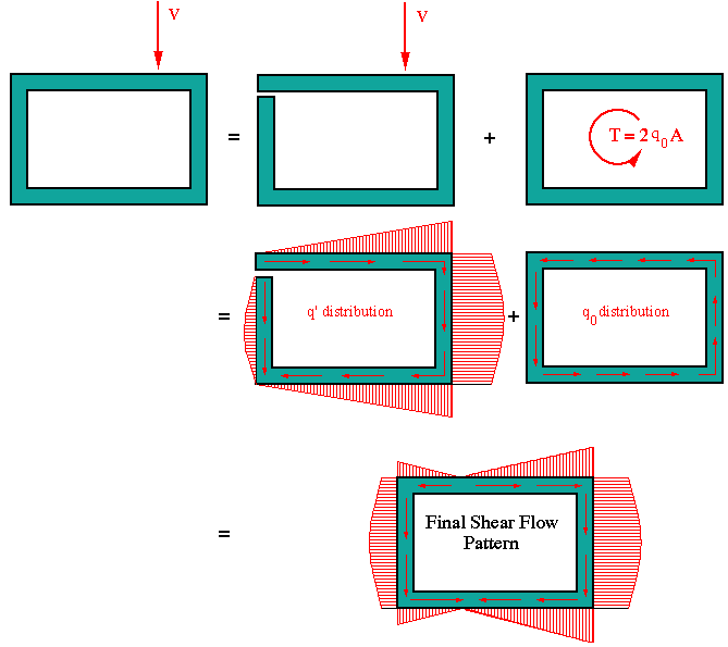
As in the previous case, we begin the analysis by selecting a point and assuming that q' = 0. Then we use the general shear flow equation to determine the preliminary shear flow distribution q' all around the section. This shear flow distribution will satisfy the force equilibrium but not the moment equilibrium. To satisfy the moment equilibrium a constant shear flow q0 must be added to the preliminary shear flow system. The magnitude of this constant shear flow is found from moment equilibrium. That is the sum of moments due to the shear flow system of q'+q0 about an arbitrary point must balance the moment produced by the resultant shear force about the same point. With one equation in one unknown, the magnitude of q0 will be determined.
Note that the shear center location will remain unknown or unimportant
throughout the solution.
For our rectangular section example with the shear force shifted near the
right edge, this approach yields the final shear flow
pattern as shown below

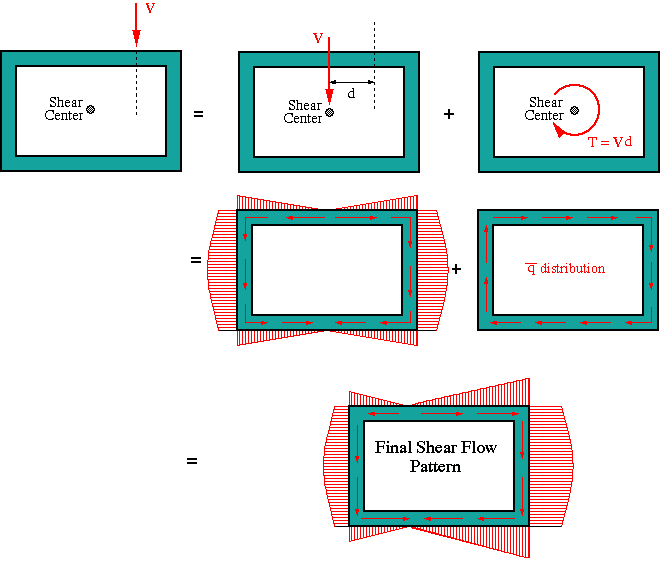
We use this method if in the process of calculating the shear flow distribution due to the applied load we also want to determine the location of the shear center. To explain this procedure let us consider the same example used for the direct method. We can represent the resultant force acting at some arbitrary location in terms of an equivalent force-moment system acting at the shear center of the section. We don't know the magnitude of the moment as we do not know the location of the shear center, but we can write it as the force times its moment arm, measured from the point of application of the force to the shear center as shown in the figure below.
Now we solve the problem in two parts. First we determine the location of the shear center by determining the shear flow distribution due to force through the shear center. The procedure is exactly the same as the one described above in the bending problem.
At the conclusion of this part, we know the location of the shear center. If the location of shear center is exactly along the line of action of the applied force as specified in the problem (i.e., d = 0), then the solution is finished. Otherwise, we calculate the moment shown in the figure as T = Vd. This moment has a shear flow associated with it which can be found using the relation T = 2qA. From this relation we solve for the constant shear flow shown in the figure as qbar. This shear flow has to be superimposed over the one found previously, in the shear center calculation, in order to get the final shear flow distribution corresponding to the actual loading condition.

 To Section IV.2
 To Index Page of
Transverse Shear Loading of Closed Sections