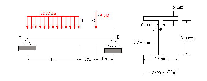


(a) To find the maximum transvere shear, the shear at each section along the beam between sections A and D must be found. This means that we need to draw the shear diagram. To do this we have to take the following steps:
From the free body diagram, the reactions at A and D are
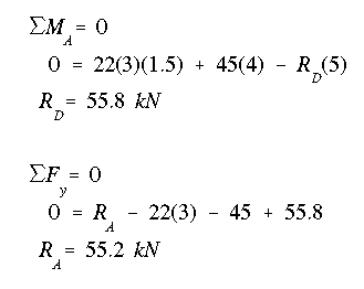
The transverse shear can be found by using the integral equation from mechanics of materials
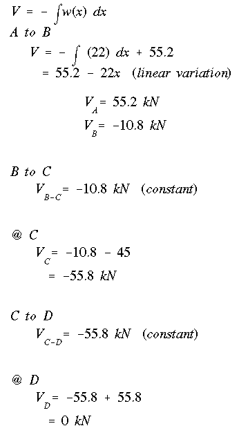
The resulting shear diagram shown below indicates that the maximum shear force is Vmax = 55.8 kN and it occurs along portion CD.
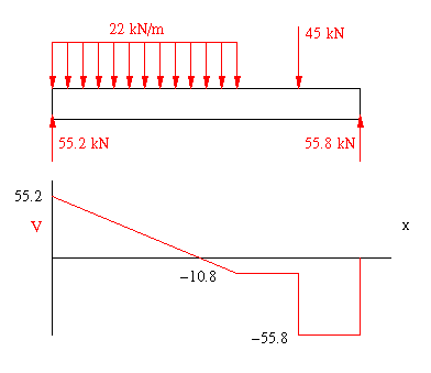
Notice that the answer to part (a) is the same as the one found in Example 1. This is because the beam supports and loading condition dictate the transverse shear force variation along the length of the beam. The shape of the beam cross section has no effect on this variation.
(b) For the shear flow calculation, with the shear force and the moment of inertia about the horizontal centroidal axis known, we again begin from a free end where we know the shear flow is zero. In this case, we start from the free end of the top right flange. Note that we could have chosen any of the three free ends of the cross section. The final variation would come out to be exactly the same regardless of which flange tip we started from.
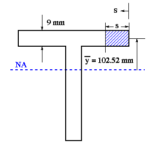
For the segment of length s, write the moment of area equation and put it in the shear flow equation as given below.
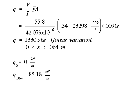
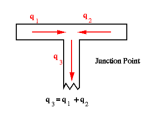
Due to symmetry about the vertical centroidal axis, the shear flow in the top left flange will be the same as the flow in the top right (same magnitude, opposite direction).
For the web, begin at the web-flange junction. What pours into the web is what enters the junction from each flange.
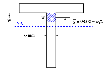
Consider the segment of length w along the web. Write the equation for its moment of area, and put it in the shear flow equation as in Example 1.
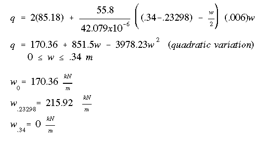
The final shear flow diagram is shown below. Note the linear variations in horizontal flanges and quadratic variation in the vertical flange.
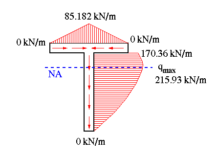
If we integrate the shear flow equation for the vertical flange we obtain a shear force of 55.02 kN. This is approximately 99% of the total shear force of 55.8 kN. The remaining 1% is carried by the horizontal flanges.
(c) Do to symmetry about the vertical axis, the shear center falls along that axis, but not at the centroid as was the case with doubly symmetric I cross section of beam in Example 1. With the shear center falling on the vertical axis of symmetry its x-coordinate measured from the centroid is obviously zero.
(d) The maximum shear stress will occur at the point on the cross section where (q/t) is maximum. In this case maximum shear stress occurs at the neutral axis and its value is
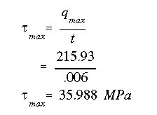
To summarize, the maximum shear stress in the horizontal flanges occur at their respective junction with the vertical flange. This shear stress is 9.02 MPa. The minimum shear stress in the vertical flange is 28.39 MPa and the maximum shear stress is 35.99 MPa.
 To Next Example
 To Index Page of
Transverse Shear Loading of Open Sections