
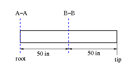
First define stations A-A and B-B. Since we are looking for the shear flow at the root, let that be station A-A. This is a cantilever beam with constant cross section, therefore station B-B can be anywhere between station A-A and the tip. Since the cross-sectional properties are constant along the length of the beam, the magnitude of the shear flows will be independent of the location of station B-B. In this example, station B-B is placed at 50 inches from the tip.
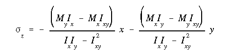
Using equation A13.13, the normal stress in each stringer is found (remember that the stringer coordinates are in reference to the centriod).
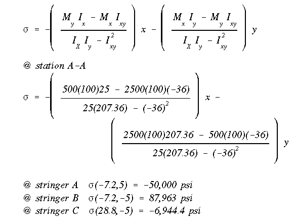
The normal force is just the stress times the area.

Now repeat the procedure for B-B. If this cross section and/or the stingers varied with the length, then the moments of inertia and centroid would need to be calculated again. But in this case they don't. We just need to recalculate the bending moments as the moment arms are different for station B-B.
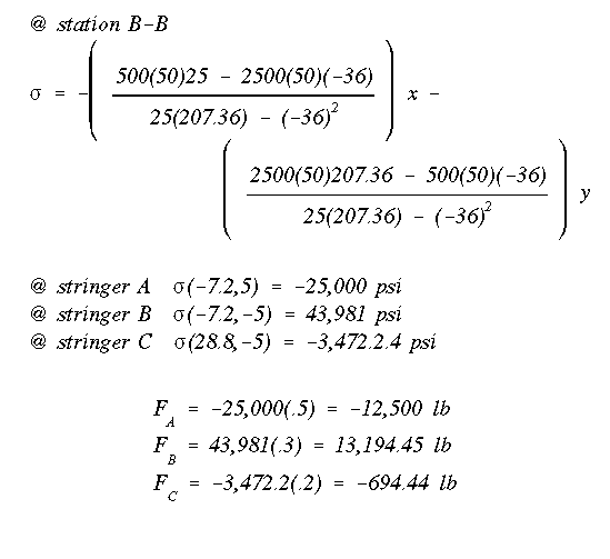
The delta P's (i.e., the difference in the axial forces at the ends of each stiffener between stations A-A and B-B) are:
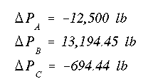
Remove the necessary webs to make this an open section. Webs AB (the quarter circle) and web AB (the interior web) are removed in this example. Now calculate the shear flow for the cross section. Here is the way of finding the shear flows. Starting at 'A', show the dP found earlier in the proper direction.
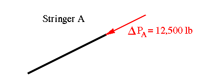
In order to maintain equilibrium, there must be another force in the opposite direction. This force can either be represented as a force or a shear flow along the right edge of stringer A where it is attached to a web.

The shear flow in the web that is attached to stringer A is of equal magnitude but of opposite direction due to equilibrium requirements. The same is seen in stringer C. Note that since the web is rectangular, the shear flow along all four sides would be equal.
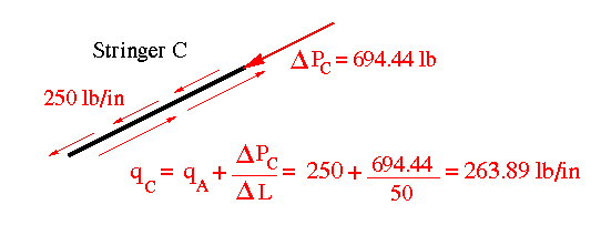
Stringer C has a shear flow of 250 lb/in on the left side. In addition, it has a dP of 694.44 lb. Hence, in order to maintain equilibrium there is a need for another shear flow along the right edge of stringer C. This shear flow is calculated in the figure below.
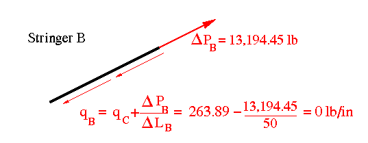
This new shear flow is passed onto the bottom web, then onto stringer 'B' which already has a dP acting on it.
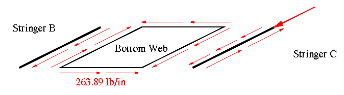
Since B is the last stringer having a free edge on the left, the force acting along that edge should come out zero. If it doesn't, then something is wrong in the calculations.
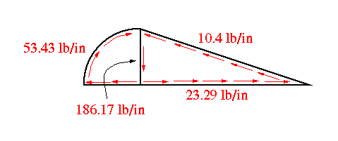
 Here is a full picture of this process.
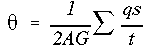
It is important to note that the shear flows calculated so far are not the final answers. This is evident by the fact that these shear flows satisfy only the force equilibrium and not the moment equilbrium. Now, we replace the webs that were removed earlier and write the angle of twist equation for each cell in terms of the two unknown constant shear flows (one for each cell) q1 and q2. Since the angle of twist in cell one is the same as that in cell two, we get one equation at the end in terms of q1 and q2 only.


Next, we sum the moments about 'A' to get another equation in terms of the two constant shear flows. Notice that the moment due to external forces is zero due to the location of the moment center.

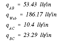
Solving the two equations simultaneously gives q1 and q2. The final shear flows at the root section are given below:
 To Section IV.5
 To Index Page of
Transverse Shear Loading of Closed Sections
To Index Page of
Transverse Shear Loading of Closed Sections