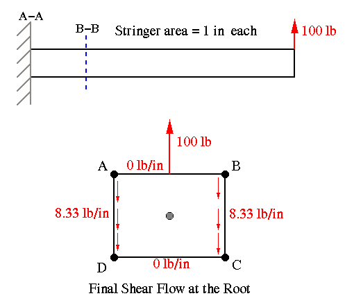
The Delta P method described in this section is what we would use for nonuniform beams. Note that nonuniformity could be in different forms. For example, we could have a skin-stringer box beam with stringer areas varying along the length of the beam causing the moment of inertia to be a function of position along the length. We could also have webs of varying dimensions, i.e., tapered . The shear flow analysis using the Delta P method is more tedious than using the general shear flow equation and is not recommended for uniform beams.
The example problem below shows the procedure for using the Delta P method. Let's consider a square beam of 100 in. in length subject to a 100 lb load at its tip passing through the centroid. There are four stringers at the corners, each with an area of 1 sq. in. We'd like to find the shear flow pattern by using the Delta P method.

The final shear flow pattern is shown above. The following solution steps show how this pattern was obtained.
With Delta P method we must identify two adjacent sections along the length of the beam. The section at which the shear flows are sought is called section A-A, and the adjacent section, some distance away along the length, is called section B-B.
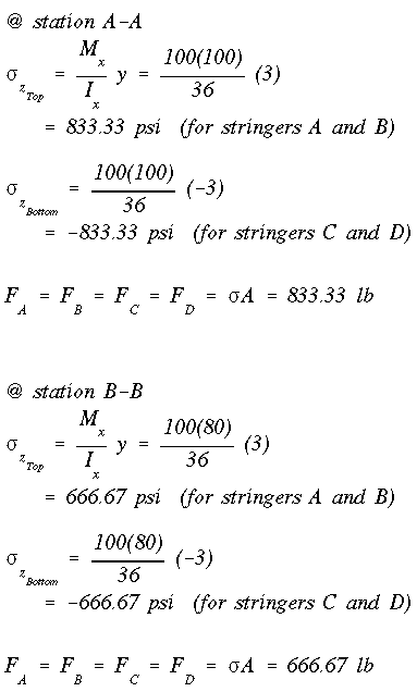
We proceed by calculating the normal force in each stringer at section A-A. To do this we need to use the general bending stress equation. First, we need to identify whether there is any symmetry with respect to horizontal or vertical centroidal axes. This is done by examining the stringer areas and their distribution. Also determine how many components of bending moment are present at section A-A. In this case the cross section is doubly symmetric, so obviously the product of inertia is zero. Also with the force at the tip acting in the vertical direction, there is only one moment at the root, that is Mx. Once the stress in each stringer is determined, the force in each stringer is determined by the product of stress times the cross-sectional area.
These steps are repeated at section B-B. Notice that this section is closer to the tip, therefore, the bending moment at this section is less than that at the root, section A-A. Since there is no change in cross-sectional geometry, the centroidal location and the moment of inertia do not change. The forces in stringer at section B-B are obtained and shown below.
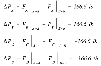
The difference between the axial force at each end of the stringer is determined next. This is where the name Delta P comes from.
As in previous method of solution based on Eqn. A14.14, we must begin at a point with known shear flow. So we cut the box beam along one web which would make shear flow zero there. Then we start with stringer A and calculate the shear flow along the 5" length (i.e., the distance between sections A-A and B-B) by dividing the Delta P of stringer A by 5". This shear flow has to be equal to that in the adjacent web at the top. Since the web is untapered, the shear flow along all four sides would be equal. We march around the entire section and find the shear flow in each web. Notice that equilibrium is maintained in each stringer and in each web as it must. Please note carefully the directions of the forces and shear flows. You can click on the picture for a more detailed drawing of the stringers. Each stringer and web is in equilibrium, this can be proven by summing the forces.
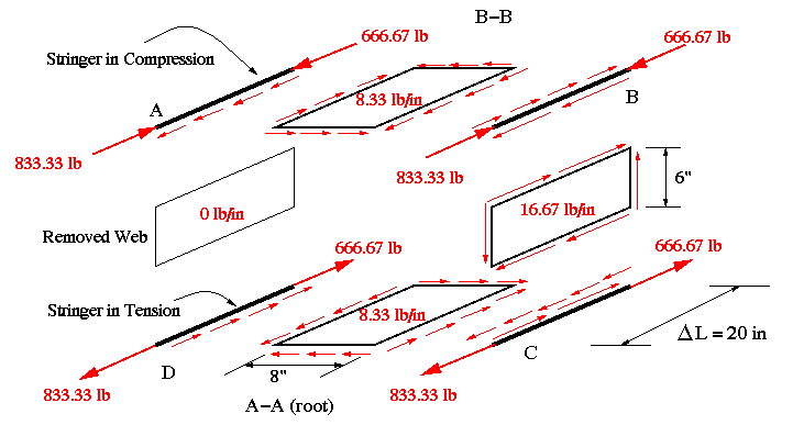
Next, we close the section by replacing the cut web. To calculate the shear flow along the web that was set to zero, we use the moment equilibrium equation. This equation gives the constant shear flow qo. This value is then added (with attention to direction) to other shear flows to obtain the final shear flow pattern at the root, section A-A.
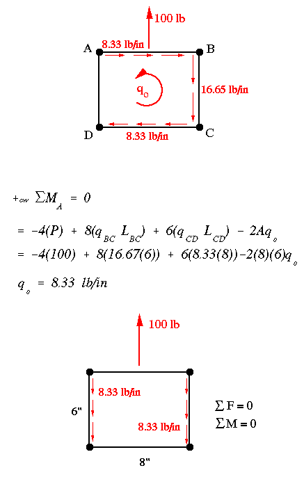
What we just did is the Delta P method in a nut shell. Notice how the shear flows are exactly the same as found before. Because this beam has no taper along its length, we could have taken station B-B to be anywhere along the length and still get the same shear flows at the root. This, however, is not the case in tapered beams, as we will discover next.
 To Section
IV.6
 To Index Page of
Transverse Shear Loading of Closed Sections